PET-EPRI Scanner
Combined Positron Emission Tomography (PET) - Electron Paramagnetic Resonance Imaging (EPRI)
The advent of hybrid scanners, merging complementary modalities, has revolutionized imaging. The standard paradigm is to combine a structural imaging modality with a functional modality. In this project, we propose a shift of this paradigm by investigating the melding of two complementary, functional imaging methods. Specifically, we plan to integrate positron emission tomography (PET) with electron paramagnetic resonance imaging (EPRI). EPRI is a relatively new method, capable of mapping quantifying extracellular parameters (pH, for example), while PET can quantify intracellular physiology (glycolysis, for example). Thus, a combined PET/EPRI scanner promises to provide new insights into dynamic physiologic interactions in microenvironments not currently attainable with current hybrid imagers. Development of the system is technically challenging, requiring unique approaches to scanner design, construction and testing.
The potential advantages and cross-modality interactions between PET and EPRI scanners were explored by construction of a prototype combined system. The PET scanner used in this study was constructed at West Virginia University as part of a continuing effort to produce images of the brains of ambulatory subjects. It consists of a ring of twelve detector modules (inner diameter= 21 cm). Each module contains a 32 ´ 32 array of polished LYSO detector elements (1.5 mm x 1.5 mm x 10 mm), separated by 0.07 mm thick ESR reflector (Proteus, Chagrin Falls, OH). The twelve scintillation blocks are individually coupled to 10 x 10 arrays of 3 mm x 3 mm (4.85 mm pitch) S10362-series MPPCs (multi-pixel photon counters) (Hamamatsu Photonics, Shizuoka, Japan). The MPPCs are readout with multiplexed, 4ch-readout electronics (AiT Instruments, Newport News VA). The forty-eight amplified analog signals are digitized with an FPGA-based, 64-channel data acquisition module (AiT Instruments, Newport News, VA). These data are used to create three-dimensional maps of radiotracer distribution with the MLEM (Maximum-Likelihood Expectation-Maximization) iterative reconstruction algorithm. The spatial resolution of the system is 2.2 mm (full width-at-half-maximum (FWHM) 5mm from center of scanner); peak detection sensitivity is 0.5%.
The EPR imager was constructed at West Virginia University as part of an ongoing effort to explore and advance EPRI methodology. It utilizes the recently developed rapid scan (RS) EPR technique (RS-EPR). The EPRI configuration used for co-imaging with the PET system is similar to one previously described by Tseytlin, et al. . The EPRI resonator unit is based on the design described by Hirata et al. . It consists of an RF surface loop (into which the sample is placed) connected to a distributed capacitor network containing two 50 Ohm coaxial cables and a coupling unit that matches the resonance structure to the 50 Ohm transmission line. The unit also contains a l/2 balun. The constant magnetic field necessary to produce the EPR signals is supplied by a permanent dipole magnet (Ningbo Jansen NMR Technology, Co). It has a pole-to-pole gap of 12.5 cm and produces a magnetic field of ~268 G corresponding to ~750 MHz for an EPR spin probe with a g-factor of ~2. Elements of a Helmholtz coil are mounted on the magnet poles to facilitate fine tuning of the magnetic field up to ~293 G (820 MHz). The EPR spectra of the probe used in this investigation has two components, Gaussian and Lorentzian. The width of the Lorentzian component (EPRI-Lw) was extracted from the spectral data using a line fitting procedure; its value is related to the presence of oxygen, or other paramagnetic compounds. The integral of the EPR spectra intensity is related to probe concentration (EPRI-Conc). Four-dimensional images (three spatial axes and one spectral) of EPRI-Lw and EPRI-Conc were reconstructed using the iterative backprojection method. The nominal EPRI image voxel size is 0.25 mm x 0.25 mm x 0.25 mm.
A multi-modality phantom was designed and fabricated with a FormLabs (Somerville, MA USA) Form2 3D printer. It has an outer diameter of 10.7 mm and contains four 254 ml cylinders (3 mm inner diameter; length= 36 mmm; center-to-center distance= 4.6 mm). The cylinders were filled with specially-formulated, PET-EPR imaging solution. Specifically, an oxygen reporting spin probe, per-deuterated ‘Finland’ triarylmethyl (trityl) radical (dFT), was used to produce EPR signals. Since it is difficult to accurately control oxygen concentration in the phantom, 1 mM of gadolinium contrast agent (Gd-DTPA, BioPAL, Worcester, MA USA) was added to 1 mM of dFT to emulate the presence of oxygen. Gadolinium shortens the relaxation times of the EPR probe by the same exchange interaction mechanism as oxygen. The PET radiotracer 18F-FDG was added to the EPR probe solution to create the dual-modality tracer. Two variants of PET-EPRI imaging solution were created. One contained 1mM of dFT, 1 mM of Gd and 25mCi of FDG (defined as the Gd+F- solution). The second contained 1mM of dFT and 49mCi of FDG (defined as the GdoF+ solution). This concentration of dFT is comparable to that measured in vivo. Indigenous oxygen in the solutions was removed by adding glucose (10mM, Sigma Aldrich, Cleveland, OH USA) and glucose oxidase (500 U/ml, Sigma Aldrich, Cleveland, OH USA). To make up the required vo lume of the samples (254ml), appropriate amounts of 0.1 M Na-phosphate buffer (pH= 7.4) were added. The phantom was filled such that diagonally opposed cylinders contained the same solution type.
To create the prototype PET/EPRI scanner, the PET detector ring was placed in the center of the dipole magnet (to permit access to the center of the PET scanner, it was tilted by approximately 20°) (Fig. 1). The EPR system’s rapid scan coils were placed in the center of the PET ring. The EPR RF loop holding the phantom was inserted into the center of the PET-RS-coil combination. The orientation of the RF field is parallel to the axis of the loop. PET and EPRI data were obtained simultaneously for 3 min. Images were created as described above. Following the PET-EPRI scan, the phantom was placed in a 1 T small animal ICON MRI scanner (Bruker, Billerica, MA USA) (T1 FLASH; TR= 41ms; TE= 4.8ms; flip angle= 30°; image voxel size= 0.25mm x 0.25mm x 2.4mm). Prior to registration, the MR, PET and EPR images underwent rigid body rotation and scaling based on their relative orientations and image pixel sizes. Registration was performed by overlaying the transformed images utilizing the Photoshop image processing software (San Jose, CA USA). While PET and EPRI can produce quantitative images, for this initial investigation we chose to only make qualitative comparisons between images from the modalities to simplify imaging processing. Thus, image intensities are utilized to represent relative radiotracer concentration, dFT probe concentration and simulated oxygen concentration.
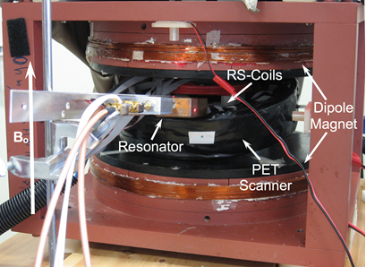
Fig. 1: Picture of the complete PET-EPRI system (orientation of the magnetic field is shown).
Figure 2(a) shows the T1-weigted MRI image of the phantom (the light gray semi-circles at the top corners are images of two small vials of water included with the phantom to facilitate tuning of the MRI scanner). The PET image in Fig. 2(b) illustrates the differences in FDG concentration of the two solutions based on relative image intensity. Importantly, there are no photon attenuation artifacts apparent in the images. Fig. 2(c) shows a map of the Lorentzian contribution to the EPR signal line width (EPRI-Lw), which is related to pO2 in the sample (line width is measured in milli-Gauss). The image in Fig. 2(d) is a map of the intensity integral of the EPR spectra related to the concentration of dFT in the solutions (EPRI-Conc). Importantly, there are no cross-modality-related artifacts in either the PET or EPR images.
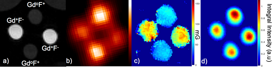
Fig. 2: Images of the multi-modality phantom a) MRI image showing the presence and absence of Gd (Gd+ or Gdo), and the presence of high or low concentration of 18F (F+ or F-), b) PET image (image intensity is related to FDG concentration), c) EPR image of Lorentzian line width (EPRI-Lw) (image intensity is related to oxygen concentration simulated using Gd) and d) EPR image of dFT concentration (image intensity is related to dFT concentration).
The next step in our continuing effort to develop a pre-clinical PET/EPRI scanner is construction of a compact, EPR-compatible PET system based on a monolithic annulus of scintillator possessing higher resolution and detection sensitivity than the current scanner. Additionally, a higher resolution, higher and more spatially-uniform sensitivity resonator will be created. Continued development of the system will also include application of established methods for quantifying and co-registering PET, EPR and MR images.
Acknowledgements
The authors thank Dr. B. Driesschaert for synthesis of the trityl radicals used in our measurements; and Drs. D. Komarov and H. Hirata for providing image reconstruction software. This work is supported by NIH/NIBIB R21 EB022775, NIH/GMS U54 GM104942, NIH P30 GM103503, NIH/NIMH R24MH106057, CA194013, CA192064 and R01 EB023888.
PET-EPRI Publications from our Group
- Tseytlin, A.V. Stolin, P. Guggilapu, A.A. Bobko, V.V. Khramtsov, O. Tseytlin, R.R. Raylman, A combined positron emission tomography (PET)-electron paramagnetic resonance imaging (EPRI) system: initial evaluation of a prototype scanner, Physics in Medicine and Biology, 2018;63(10):105010. (PubMed PMID: 29676283).